Table of Contents
Overview
Congratulations on the purchase of your MOTORplate! We believe that you'll find it the most powerful motor controller for the Raspberry Pi on the market today. Before diving into the details of your Pi-Plate, let's take a quick tour of the major features. Below, we have highlighted the major functional areas:

Raspberry Pi Header
This is the connector that attaches to the Raspberry Pi or to another Pi-Plate if you are stacking your boards. As shipped, this connector works with all versions of the Raspberry Pi. If you you need access to the extra pins of the B+, A+, and Revision 2 of the RPI then you can solder in the included 2X7 stacking connector.
Address Select Header
This header, along with the three shunts connected to it, allow you to set the address of your MOTORplate. The address can be set from 0 to 7, so up to eight MOTORplates can be used in a single stack. Note that each Pi-Plate model has a unique TYPE address so it's possible to have a MOTORplate stacked on top of a DAQCplate with both set to address 0.
Use the diagram below as a guide for setting the address of your MOTORplate:

Motor Drivers
These are two Toshiba TB6612FNG chips that interface directly to your motors. Each chip contains two H-bridges capable of driving a single bipolar stepper motor or two DC motors. They can operate with motor voltages as high as 15VDC and at an average current of 1.2 Amps and peak currents as high as 3.2 Amps. Since the H-bridge transistors are MOS instead of bipolar, these chips run cool while providing more power to the motors. An on-board microprocessor connected directly to the Raspberry Pi interfaces directly to these chips which simplifies the code required to drive a motor.
Motor Terminal Blocks
The MOTORplate has two, 10 pin terminal blocks for the attachment of motors and sensors. These are shown in the diagram below. Details on connecting to these terminals is covered in more detail below in the Connections chapter.

Motor Power Terminal Blocks
The MOTORplate has two headers that allow you to choose between three power sources for each of the motor drivers. These are shown in the diagram below. Details on connecting to these terminals is covered in more detail below.

Power
Motors come in all shapes and sizes and are designed to operate at different voltages. The equation for motor output power is Po=torque•speed. And, the equation for the motor input power is Pi=voltage•current. The efficiency of a motor is η=Po/Pi. If we combine these equations we get: torque=(voltage•current•η)/speed or speed=(voltage•current•η)/torque. Therefore, if you want more speed or torque from your motor, you will either need more voltage or current.
Most likely, you will use motors that require either a different voltage or higher power requirements than what is available from your Raspberry Pi. The MOTORplate has two headers that allow you to choose between three power sources for each of the motor drivers. A jumper on each header allows selection of:
- The 5VDC that drives your Raspberry Pi
- The power supply connected to the terminal block labeled VM1
- The power supply connected to the terminal block labeled VM2
By default, the jumpers are set to power the motor drivers directly from your Raspberry Pi 5VDC supply. However, we strongly advise against this unless you have a VERY good source of 5VDC or if you are driving small motors. Driving anything greater than 500mA will most likely cause your system to reboot from a power droop. In addition, this option only supports motors that can operate at 5VDC.

Default Power Steering Settings - on board RPI 5VDC routed to both motor drivers
To deliver more power to your motor, you should attach a separate power supply to VM1 or VM2. Then move the jumper on the power steering to the appropriate source. Remember: the voltage on these supplies cannot exceed 15VDC! Lets look at a few examples:

A Single 12VDC supply on VM1 input being routed to both motor drivers
 12VDC Supply connected to VM1 and routed to Motor Driver 2. 6VDC Supply connected to VM2 and routed to Motor Driver 1

A Single 6VDC supply on VM2 input being routed to both motor drivers
Stepper Motors
Overview
Each MOTORplate can drive two bipolar stepper motors. Stepper motors have some unique advantages as well as disadvantages over DC motors. Some of the advantages are:
- Once a start position has been established, steppers can be repeatedly driven to a specific location without any positional feed back (also known as dead reckoning)
- When stopped, steppers can maintain a holding torque
Some disadvantages include:
- The rotational resolution is coarse unless microstepping is used
- They are more complicated to drive
- They can be noisy
- They are slower
- They cannot produce as much torque
Rather than filling this document with pages and pages of detailed information regarding stepper motors we suggest you read this article from someone who is far smarter than we are on the topic.
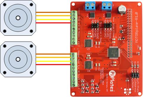
Connections
Here's an image of the motor connectors again. Note that stepper 'A' attaches to the four leftmost terminals on the left connector and stepper 'B' attaches to the four leftmost terminals on the right. See below for the use of the Sensor Inputs.
A bipolar stepper motor has the schematic shown below. As you can see, there are four wires attached to the two windings.

While there is no formal standard on the color of the wires and how they should be connected to the drivers. we did find this table at Lin Engineering that correlated to the common 1.8° per step motors that we have:

Specifically, when we used Color Code 2 and connected to the MOTORplate as shown below, we were able to drive our motors without any problems. However, some trial and error may be required to determine your motor wiring scheme if you have different wire colors. It might also help to use an ohmmeter to determine which wire pairs are attached to a coil.
Now, our motors actually have 6 wires so that they can be used in either a unipolar or bipolar configuration. However, we use the bipolar arrangement since it provides us more torque and that is what the MOTORplate is designed to support.
Control
The discussion that follows assumes that your stepper motor has a resolution of 1.8° per step or 200 steps per revolution. However, the documentation applies to bipolar stepper motors of any resolution.
Definitions
The following arguments and their definitions are used in the commands required to control stepper motors with the MOTORplate.
- addr: Address - MOTORplates have jumpers on the board that allow their address to be set to a value between 0 and 7. The location of these jumpers and their settings are discussed above.
- motor: Motor Designator - used for selecting the motor to drive. For stepper motor functions this is either an 'a' or a 'b' - the case is insensitive but the characters have to be enclosed in quotation marks. The 'a' stepper is attached to Motor Connector 1 and the 'b' stepper is driven by attached to Motor Connector 2. See the diagram above for reference.
- dir: Direction - the two accepted arguments are clockwise 'cw' and counter clockwise 'ccw' - the case is insensitive. These directions are dependent on how you have wired up your motor so, some experimentation may be required.
- resolution: Stepper Resolution - MOTORplates can drive stepper motors using four different step sizes. These can be specified with either a number or characters. Again, for characters, the case is insensitive but they have to be enclosed in quotation marks:
Full Steps: 0 or 'F'
Half Steps: 1 or 'H'
Four Microsteps: 2 or '4M'
Eight Microsteps: 3 or '8M'
The illustration below shows these four different angular resolutions:

So, if your motor moves 1.8° per step with the 'F' resolution, then setting it to 'H' or 1/2 steps will move it 0.9°, 'M4' will move it 0.45°, and M8 will move it 0.225°. M4 and M8 use microstepping techniques which provide much smoother motion with more torque but at a reduced speed. With the 'F' resolution, a 1.8° motor requires 200 steps for a complete revolution of the shaft. When the resolution is set to 'M8', a complete revolution will 1600 steps.
- rate: Stepper Rate - MOTORplates can drive stepper motors at step rates from 1 to 2000 steps per second. Values outside of these limits will produce an error. Note that the maximum step rate you can achieve is dependent on the motor, the motor voltage, the load on the motor, and the acceleration rate. Be aware that step rates move the motor at the resolution you select. For example, a step rate of 100 with a resolution of 'F' will rotate the motor shaft 100•1.8° = 180° per second. If your resolution is 'M8', the rotational speed will be 100• 0.225° = 22.5° per second.
- acceleration: Motor Acceleration Time - MOTORplates have the ability to gradually ramp up (and down) to the desired motor step rate or speed. This feature prevents the motor from stalling under high load or high speed conditions. Values for acceleration range from 0.0 for no acceleration to 5.0 seconds. Let's look at some acceleration plots to better understand this feature. The following examples are based on the same settings: a step rate of 1000 steps/second and an acceleration of two seconds.
- Example 1: A plot of step rate versus time after a stepperJOG command would look like:

- Example 2: A stepperMOVE command requesting 10,000 steps of rotation produces the following step rate versus time plot:

Note how the MOTORplate slows the motor for two seconds starting at the 8 second mark so that a total of 10,000 steps have occurred when the step rate reaches zero. - Example 3: A stepperMOVE command requesting 1600 steps of rotation produces the following step rate versus time plot:

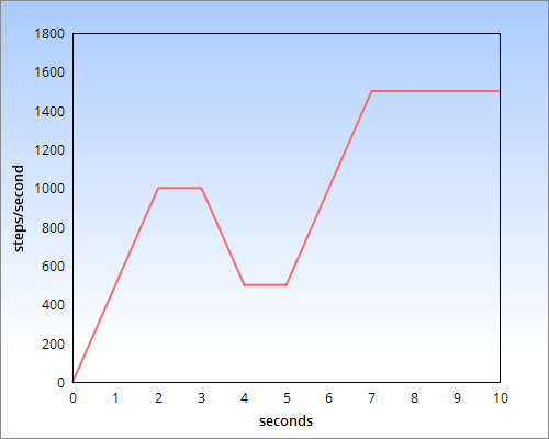
Note that since the motor is only moving a total of of 1600 steps it never reaches the final rate of 1000 steps per second. Instead, it has to start slowing down when it has rotated 800 steps. - Example 4: The following sequence of commands is applied to motor 'a' on a MOTORplate set to address 0:
MOTOR.stepperJOG(0,'a')
timer.sleep(3)
MOTOR.stepperRATE(0,'a',500)
timer.sleep(2)
MOTOR.stepperRATE(0,'a',1500)

Note that when you change the step rate of a rotating motor the acceleration values are still applied.
- Example 1: A plot of step rate versus time after a stepperJOG command would look like:
- steps: Step Count - This value is used when moving a stepper motor a fixed number of steps. The value can range from 1 to 65,535. The actual amount of travel will depend on the motor and the resolution. For example, you have a motor that rotates 1.8° per full step. If you set the resolution to 'F' and use a stepperMOVE command with 200 steps, the motor will rotate 360°.


Commands
stepperCONFIG(addr,motor,dir,resolution,rate,acceleration) - this command has to be executed to initialize a stepper motor. See the definitions above for a detailed explanation of each argument. As an example, let's configure a stepper motor connected to Motor Connector 2 on the MOTORplate at address 0. We want it to move at 1500 steps per second, turn counter clockwise with a resolution of 4 microsteps, and accelerate for 3 seconds. The configuration command to do all this would look like:
MOTOR.stepperCONFIG(0,'B','CCW','4M',1500,3)
Note:
- This command only configures the motor for motion. It will not start rotating until you issue a stepperMOVE or a stepperJOG command.
- This command can only be issued when the motor being configured is STOPPED.
stepperMOVE(addr,motor,steps) - the command will move a stepper number a fixed number of steps using the acceleration, step rate, direction, and resolution values specified in the stepperCONFIG call. As an example, let's assume that our motor has a full step resolution of 1.8° and that it has been configured using the settings described above. If we want the motor to rotate 360° the we have to tell the motor to take 4*(360/1.8)=800 steps since our resolution is 4 microsteps:
MOTOR.stepperMOVE(0,'B',800)
Note that it's possible to poll or use interrupts to detect the end of a stepper MOVE. To poll, use this command:
MOTOR.getINTflag0(0)
This will return an 8 bit number with the following information:
Bit 7: Not Used
Bit 6: Not Used
Bit 5: Stepper A MOVE Complete
Bit 4: Stepper B MOVE Complete
Bit 3: Sensor 4
Bit 2: Sensor 3
Bit 1: Sensor 2
Bit 0: Sensor 1
The snippet of python code below demonstrates a simple polling loop:
|
1 2 3 4 5 6 7 8 9 10 11 |
import time #import the time module import piplates.MOTORplate as MOTOR #import the MOTORplate module MOTOR.stepperCONFIG(0,'a','cw','M8',2000,2) #configure stepper A MOTOR.stepperMOVE(0,'a',1600) #Start a MOVE of 1600 steps flag=1 #Initialize flag to true while(flag): #start loop time.sleep(0.1) #check every 100msec stat=MOTOR.getINTflag0(0) #read interrupt flags if (stat & 0x20): #isolate and test bit 5 flag=0 #if bit 5 is true then clear the flag print "Move Complete!" #Celebrate! |
Note that reading the interrupt flag register also clears it. See the the section below to learn how to detect the end of the move using interrupts.
stepperJOG(addr,motor) - this command will instruct the specified stepper to rotate indefinitely using the acceleration, step rate, direction, and resolution values specified in the stepperCONFIG call. For example, assume we have already configured stepper motor A on the MOTORplate at address 0 to rotate clockwise using half-steps at a speed of 250 steps per second with a 1 second acceleration:
MOTOR.stepperCONFIG(0,'A','CW','H',250,1)
To start this motor rotating we simply follow the above statement with:
MOTOR.stepperJOG(0,'A')
The motor will accelerate to 250 half steps per second moving clockwise.
stepperSTOP(addr,motor) - this will instruct the specified jogging stepper to come to a stop using the acceleration value specified in the stepperCONFIG call. If the acceleration value is set to zero the motor will stop instantly. Once stopped, current will continue to flow through the windings to maintain the hold torque. For example, stepper 'A' on the MOTORboard at address 0 has been jogging for a few minutes and we need to stop it:
MOTOR.stepperSTOP(0,'A')
Note that this command can only be issued when the motor is rotating at a steady step rate and NOT during acceleration or deceleration.
stepperRATE(addr,motor,rate) - this will change the step rate of a jogging or stopped stepper motor. If the the motor is spinning at a steady state the step rate will change using the acceleration value specified in the stepperCONFIG call. If the motor is in the process of accelerating, decelerating, or stopping, this command will be ignored. Recall example 4 in the discussion of acceleration:
MOTOR.stepperCONFIG(0,'a','cw','H',1000,2)
MOTOR.stepperJOG(0,'a')
timer.sleep(3)
MOTOR.stepperRATE(0,'a',500)
timer.sleep(2)
MOTOR.stepperRATE(0,'a',1500)

Once the motor was at a stable rate of 1000 steps per second, we issued the MOTOR.stepperRATE(0,'a',500) command to slow it down to 500 steps per second. After deceleration and jogging at this rate for 2 seconds we issued the MOTOR.stepperRATE(0,'a',1500) command to ramp it up to 1500 steps per second. Note that these commands were issued while the motor was rotating at a steady rate.
stepperOFF(addr,motor) - remove power from a stopped motor. Use this function to reduce your power consumption and keep your motors cool. If not used, the current will continue to flow through the stepper windings maintaining the hold torque.
End Stops / Limit Switches
While stepper motors do not require position feedback, it is common to use a sensor to detect a start or reference position. For example, if you use a stepper motor to move a mechanical stage, you will likely move that stage to a known position at power up. Usually, that position is at the end of the travel range and an end stop sensor is used to detect when the stage has moved to this point.
Each motor connector on the MOTORplate has two general purpose digital inputs as well as two 5VDC outputs and two grounds. Together, the pins can be used to power and read up to two end stop sensors. Let's look at two examples:
- A Simple Leaf Switch

When the motor-driven stage comes in contact with the arm of the switch it will cause the normally open contacts to close. This in turn, will pull current through the 10K ohm pull up resistor that is on the MOTORplate causing the input to switch from high to low. - An Optical Interrupter
Another common implementation of an end stop sensor is to use an optical interrupter. Here's are the connections that will allow you to interface an H21A1 to the the Sensor 1 input on the MOTORplate:


The 150 ohm resistor limits the current into the emitter LED to about 20mA. This will shine IR light onto the detector transistor which, in turn, will pull current into its collector pin. This current will flow through a 10K pull up resistor that is part of the Sensor 1 circuit on pin 6. Under these conditions, Sensor 1 will read 0. If something is placed into the slot and interrupts the light from the LED, the transistor will turn off, and Sensor 1 will read 1.


There are two different methods to monitor the limit switches: polling or interrupts. To poll simply execute the function getSENSORS(addr) where addr is the address of the MOTORplate. This will return an eight bit number with the sensor status located in the last four bits:
| Sensor Input 4 | Sensor Input 3 | Sensor Input 2 | Sensor Input 1 |
The code snippet below assumes that Sensor Input 1 is connected to an End Stop switch for stepper motor A:
|
1 2 3 4 5 6 7 8 9 10 11 |
import time #import the time module import piplates.MOTORplate as MOTOR #import the MOTORplate module MOTOR.stepperCONFIG(0,'a','ccw','M8',1600,2) #configure stepper A MOTOR.stepperJOG(0,'a') #Start JOG flag=1 #Initialize flag to true while(flag): #start loop time.sleep(0.1) #check every 100msec stat=MOTOR.getSENSORS(0) #read interrupt flags if (stat & 0x1): #isolate and test bit 0 flag=0 #if bit 0 is true then clear the flag print "End Stop Reached!" #print notice |
See the the section below to learn how to monitor sensors using interrupts.
DC Motors
Overview
The MOTORplate can drive up to four DC motors at voltages as high as 15V and currents as high as 1.2A average. Below is a brief description of DC motors from Freescale Electronics. Click HERE for an app note from Microchip for more detailed information regarding DC motors.
The DC motor is a rotating electric machine designed to operate from source of direct voltage. The basic type is a permanent magnet DC motor. The stator of a permanent magnet DC motor is composed of two or more permanent magnet pole pieces. The rotor is composed of windings that are connected to a mechanical commutator. The opposite polarities of the energized winding and the stator magnet attract and the rotor will rotate until it is aligned with the stator. Just as the rotor reaches alignment, the brushes move across the commutator contacts and energize the next winding.
 The stator is the stationary outside part of a motor. The rotor is the inner part which rotates. In the motor animations, red represents a magnet or winding with a north polarization, while green represents a magnet or winding with a south polarization. Opposite, red and green, polarities attract.
The stator of a permanent magnet DC motor is composed of two or more permanent magnet pole pieces. The rotor is composed of windings which are connected to a mechanical commutator. In this case the rotor has three pole pairs. The opposite polarities of the energized winding and the stator magnet attract and the rotor will rotate until it is aligned with the stator. Just as the rotor reaches alignment, the brushes move across the commutator contacts and energize the next winding. In the animation the commutator contacts are brown and the brushes are dark grey. A yellow spark shows when the brushes switch to the next winding.
Notice that the comutator is staggered from the rotor poles. If the connections of a DC motor are reversed the motor will change directions; though it will not always work as well in both directions.
Some good motor candidates can be found at Pololu and The RobotShop. The high power micro gear motors from Pololu would work very well with the MOTORplate. What is especially interesting about these is that they have versions that can be configured with encoders that can be used with the tachometer inputs that we'll discuss below.

Connections
Each Motor Connector can drive two DC motors for a total of 4 motors per board. The pictures and images below illustrate how these connections should be made.
The image below shows four DC motors attached:
Or you can mix motors and have 2 DC motors and a stepper motor. The below shows a stepper on Motor Connector 1 and the two DCs on Motor Connector 2. However, these can be flipped with the stepper on 2 and the DCs on 1.

Control
Definitions
The following arguments and their definitions are used in the commands required to control stepper motors with the MOTORplate.
- addr: Address - MOTORplates have jumpers on the board that allow their address to be set to a value between 0 and 7. The location of these jumpers and their settings are discussed above.
- motor: Motor Designator - used for selecting the motor to drive. For dc motor functions this is a number from 1 to 4. DC motors 1 and 2 attach to Motor Connector 1 and motors 3 and 4 attach to Motor Connector 2. See the diagram above for reference.
- dir: Direction - the two accepted arguments are clockwise 'cw' and counter clockwise 'ccw' - the case is insensitive. These directions are dependent on how you have wired up your motor so, some experimentation may be required.
- speed: Motor Speed - MOTORplates can drive DC motors with 10 bit accuracy using the speed argument. This will be a value between 0.0 and 100.0%. Simply enter the number - do not use the percent symbol. The actual speed that your motor can spin is dependent on the motor, the voltage, the gear ratio if you're using a gearbox and of course the value of the speed variable. It is not uncommon to have tachometer feedback with DC motor - a topic we will discuss below.
- acceleration: Motor Acceleration Time - MOTORplates have the ability to gradually ramp up (and down) to the desired motor step rate or speed. This feature prevents the motor from stalling under high load or high speed conditions. Values for acceleration range from 0.0 for no acceleration to 5.0 seconds. See the illustrations above for stepper motors.
Commands
dcCONFIG(addr,motor,dir,speed,acceleration) - this command has to be executed before starting up one of the DC motor outputs. See the definitions below for a detailed explanation of each argument. Here is an example of DC motor 2 on a MOTORplate at address 0 being configured for clockwise motion at a 50% duty cycle and 2.5 seconds of acceleration:
MOTOR.dcCONFIG(0,2,'cw',50.0,2.5)
dcSTART(addr,motor) - this command will instruct the specified DC motor to start running using the acceleration, speed, and direction values specified in the dcCONFIG call. This function can also be called to restart a stopped DC motor. To start the motor we configured in the last step we issue the following command to the MOTORplate:
MOTOR.dcSTART(0,2)
dcSPEED(addr,motor,speed) - use this function to change the speed of a stopped or running motor. If this command is issued while a motor is accelerating or decelerating it will be ignored.
dcSTOP(addr,motor) - this command will instruct the specified DC motor to come to a stop using the acceleration value specified in the dcCONFIG call. If the acceleration value is set to zero the motor will stop instantly.
The following code snippet provides examples of each of the above commands:
|
1 2 3 4 5 6 7 8 9 10 11 |
import time #import the time module import piplates.MOTORplate as MOTOR #import the MOTORplate module MOTOR.dcCONFIG(0,2,'ccw',50.0,2.5) #configure dc motor 2 on the MOTORplate at address 0 being configured for clockwise #motion at a 50% duty cycle and 2.5 seconds of acceleration MOTOR.dcSTART(0,2) #Start DC motor time.sleep(5.0) #delay 5 seconds MOTOR.dcSPEED(0,2,100.0) #increase speed to 100% time.sleep(10) #wait 10 seconds MOTOR.dcSTOP(0,2) #stop the motor time.sleep(2.5) #wait for deceleration print "DC Motor demo completed" #print notice |
The above will produce the following speed versus time profile:

Tachometers
Unlike stepper motors, DC motors do not provide predictable speeds. To regulate the speed of a DC motor, you have to attach an encoder to it and count the pulses it produces using a tachometer. Using software, you compare the tachometer value to your desired rotational rate and adjust your speed up or down to correct it. Some sample encoders look like:
 Using a slotted disk and an Opto Interrupter
 A Pololu Micro Gear Motor with a Hall Sensor Based Encoder
Each of the Sensor Inputs on the MOTORplate can be used as 64 bit tachometers. That means they can count up to 65,535 pulses per second. Note that most encoders produce multiple pulses for each rotation of the motor shaft. This is important if you motor is geared down - which is highly likely. For example the encoder shown in the Pololu motor above produces 12 pulses for every motor rotation. And since the above motor is also geared down 100:1, the encoder will produce 1200 pulses for each rotation of the shaft. This approach provides much higher resolution for the feedback loop.
On the MOTORplate the tachometers are always running and require no setup. You simply connect the output of your encoder to the input and it starts counting pulses. There are two functions that provide a trade off between accuracy and speed:
getTACHcoarse(addr,tachnum) - the coarse tachometer value is a sixteen bit number that is updated eight times per second and will not be as accurate as the value obtained with the getTACHfine function since the three least significant bits are padded with zeros.
getTACHfine(addr,tachnum) - this is a much more accurate 16-bit tachometer value that is updated once per second.
In the above functions:
addr is the address of the MOTORplate
tachnum is the Sensor Input number.
As an example, let's look at a code snippet that uses a simple control loop to drive a DC motor that has a slotted encoder on the main drive shaft. There are 20 slots in the encoder and we want the motor to spin at 60RPM:
|
1 2 3 4 5 6 7 8 9 10 11 12 13 14 15 16 17 18 19 20 21 22 23 24 25 26 |
import time #load time module import MOTORplate as MOTOR #load MOTORplate module gain = .1 #set the loop gain rpm=60.0 #set the desired RPM set=20.0*rpm/60.0 #convert desired RPM to pulses per second speed=50.0 #start with a drive of 50% MOTOR.dcCONFIG(0,3,'cw',50,0) #config MOTOR.dcSTART(0,3) #and start MOTOR.getTACHfine(0,1) #flush out tachometer register try: while(1): time.sleep(.25) #sleep 250msec tach=MOTOR.getTACHfine(0,1) #get fine tach value error=set-tach #calculate difference between measured and # desired speed speed=speed+gain*error #multiply error by loop gain and adjust speed if (speed>100): #perform upper and lower limit checks speed=100 if (speed<0): speed=0 print 'speed:',speed,'tach:',tach,'rpm',tach*3,'error:',error MOTOR.dcSPEED(0,3,speed) #update speed except KeyboardInterrupt: MOTOR.dcSTOP(0,3) #shut down with keyboard interrupt |
Other Features
Interrupts
Interrupts are an alternative to polling your Pi-Plate while waiting for it to complete a task. And the MOTORplate can be configured to generate interrupts for a variety of events. These include:
- A change on a sensor input - useful for detecting an end stop sensor
- When a motor has reach a stable speed or step rate - useful for knowing when acceleration or deceleration have completed
- When a motor has stopped
What follows is a description of each function and an example that demonstrates the use of interrupts with a stepper motor.
General
intEnable(addr) - enable interrupts from the MOTORplate. GPIO22 will be pulled low if an enabled event occurs.
intDisable(addr) - disables and clears all interrupts on the MOTORplate.
getINTflag0(addr) - returns the 8 bit interrupt flag0 value then clears the register. The contents of this register are:
|step A STEADY|step B STEADY|step A STOPPED|step B STOPPED|Sense1|Sense2|Sense3|Sense4|
getINTflag1(addr) - returns the8 bit interrupt flag1 value then clears the register. The contents of this register are:
|DC 1 STEADY|DC 2 STEADY|DC 3 STEADY|DC 4 STEADY|DC 1 STOPPED|DC 2 STOPPED|DC 3 STOPPED|DC 4 STOPPED|
Stepper Specific
enablestepSTOPint(addr,motor) - generate interrupt when stepper motor has come to a complete stop. Useful for knowing when a move command has completed or when a motor has come to a stop under acceleration and deceleration conditions.
disablestepSTOPYint(addr,motor) - turn off the STOP interrupt
enablestepSTEADYint(addr,motor) - generate interrupt when stepper motor speed has reached a steady rate. Useful for knowing when a rate change can be applied under acceleration and deceleration conditions.
disablestepSTEADYint(addr,motor) - turn off the STEADY interrupt
|
1 2 3 4 5 6 7 8 9 10 11 12 13 14 15 16 17 18 19 20 21 22 23 24 25 26 27 28 29 30 31 32 33 34 35 36 37 38 39 40 41 42 43 44 45 46 47 48 49 50 51 52 53 54 55 56 |
import piplates.MOTORplate as MOTOR import RPi.GPIO as GPIO import random import time import os print MOTOR.getID(1) dummy=MOTOR.getINTflag0(1) #flush out any old interrupts intFLAG=0 intITS=0 ## interruptREG0: |step A STEADY|step B STEADY|step A STOPPED|step B STOPPED|Sense1|Sense2|Sense3|Sense4| def moveDone(channel): global intBITS, intFLAG intBITS=MOTOR.getINTflag0(1) #get flags intFLAG=1 #signal main program that an interrupt occurred def newA(): rate=random.randint(500, 2000) #randomize step rate acc=random.uniform(0,5.0) #randomize acceleration dTest=random.randint(1, 10) #randomize direction steps=random.randint(800,6400) #randomize rotation if (dTest<6): dir='cw' else: dir='ccw' MOTOR.stepperCONFIG(1,'a',dir,3,rate,acc) #Config motor MOTOR.stepperMOVE(1,'a',steps) #start move print 'Direction:',dir,'step rate:',rate,'acceleration:',acc,'step count',steps GPIO.setmode(GPIO.BCM) GPIO.setup(22, GPIO.IN, pull_up_down=GPIO.PUD_UP) #set up GPIO 22 as an input GPIO.add_event_detect(22, GPIO.FALLING, callback=moveDone) # detect interrupts MOTOR.enablestepSTOPint(1,'a') #set up to interrupt when motor a stops MOTOR.intEnable(1) #enable interrupts on Pi-Plate newA() ## MAIN LOOP try: while(1): if (intFLAG): #check to see if interrupt occurred intFLAG=0 #if INT, clear flag if (intBITS&0x20): #if motor A stopped then start new random MOVE newA() except KeyboardInterrupt: # Clean up when program is terminated go=1 while(go): if (GPIO.input(22) ==0): MOTOR.stepperOFF(0,'a') GPIO.cleanup() # clean up GPIO on CTRL+C exit go=0 GPIO.cleanup() # clean up GPIO on normal exit |
DC Specific
enabledcSTOPint(addr,motor) - generate interrupt when DC motor has come to a complete stop. Useful for knowing when a move command has completed or when a motor has come to a stop under acceleration and deceleration conditions.
disabledcSTOPYint(addr,motor) - turn off the STOP interrupt
enabledcSTEADYint(addr,motor) - generate interrupt when DC motor speed has reached a steady rate. Useful for knowing when a speed change can be applied under acceleration and deceleration conditions.
disabledcSTEADYint(addr,motor) - turn off the STEADY interrupt
LED Control
There are also functions for controlling the power LED. These are pretty self explanatory:
setLED(addr) - turn on the LED
clrLED(addr) - turn off the LED
toggleLED(addr) - if LED is on, turn off. If LED is off, turn on.