Table of Contents
Included Parts
Table of Contents
The following parts should have been included in your CASEplate kit:
| Description | Quantity | Image |
|---|---|---|
| BASE | 1 | 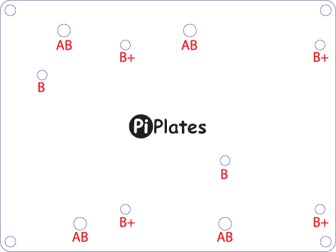 |
| TOP | 1 | |
| 25mm Nylon Standoffs | 4 |  |
| M3 Nylon Screws | 8 |  |
| M2.5 16mm steel bolt | 4 |  |
| M2.5 steel nut | 4 |  |
| #6 Steel Screw | 4 |  |
| 1/4" Plastic Spacer | 4 | |
| 1/4" Nylon Board Edge Standoff | 4 |  |
There are different ways to build up your base depending on the your Raspberry Pi version. We recommend that you sit at a table for the following steps since some of the parts are pretty small and can easily disappear. We also want to remind you to keep these parts away from small children since they present a choking hazard.
Initial Standoff Assembly
To start, locate the four 25mm (1 inch) nylon standoffs and four of the 3mm nylon screws. Then remove the protective liner from the acrylic base. Locate the four holes in the corners of the acrylic base and use the following image as a guide for screwing on the standoffs:

PCB Revision 1.0
If your Raspberry Pi looks like the following then you have a Rev 1.0 board:

Note the lack of any mounting holes of features. The four #6 steel screws and ¼" nylon board edge standoffs are required to attach this board to the CASEplate. You will need a pair of pliers and a #2 Philips head screwdriver for this step. Start by setting the base assembly on its side. Then, push a #6 screw into the bottom of the base into one of the holes labeled "AB." While holding a ¼" nylon board edge standoffs with the pliers with one hand, tighten the #6 screw with the other:

Repeat this for the other three standoffs. We have found that the best way to do this step is to tighten two of the screws along one edge while keeping the other two loose. Next, using the image below as an orientation reference, slide the Raspberry Pi into the two tightened standoffs followed by popping the two loose standoffs over the edge of the board. Tighten the two loose screws and you're done. Your assembly should look like:

PCB Revision B
If your board looks like the following then you have a revision 2.0 Raspberry Pi Model A or B:

Note the two mounting holes located on the board. Because of these hole positions, sliding the Pi-Plate on after it has been mounted using the following technique causes the board to pivot over the mounts. It's really less than ideal and we recommend that you use the Revision 1.0 mounting method described above. If however, you want to use these mounting holes then read on.
Start by locating the following hardware:
- Two M2.5 16mm steel bolts
- Two M2.5 Steel Nuts
- Two ¼ inch plastic spacers
Start by setting the base on its side and sliding the M2.5 bolts into the holes labeled "B". Then slide the spacers over these bolts as shown below:

With one hand, use your fingers to hold the bolts in place as you pick up the base and slide the Rev 2.0 Raspberry Pi onto the exposed screws. Next, loosely screw on the two M2.5 nuts - you might want to use tweezers or a pair of needle-nose pliers to hold the nut next to the USB sockets. Use a #1 Phillips head screwdriver to tighten the bolts. We have found that the easiest thing to do here is to just apply some pressure to the nut while you tighten the screw. Then, once you bottom out, give the screw diver an extra turn. When you're finished, your assembly should look like this:

B+, A+, Pi 2 and Pi 3.
The Engineers at Raspberry Pi Foundation finally got it right mechanically with the introduction of the A+ and B+ designs. Each of these have four mounting holes on a rectangular grid located close to the edge of the board. Verify that your board looks like one of the following:


Next, locate the following hardware:
- Four M2.5 16mm steel bolts
- Four M2.5 Steel Nuts
- Four ¼ inch plastic spacers
Start by setting the base on its side and sliding the M2.5 bolts into the holes labeled "B+". Then slide the spacers over these bolts as shown below:
With one hand, use your fingers to hold the bolts in place as you pick up the base and slide the Model A+ or B+ Raspberry Pi onto the exposed screws. Next, loosely screw on the four M2.5 nuts. You might want to use tweezers or a pair of needle-nose pliers to hold the nut next to the Ethernet port and the 40 pin header during this step since there's not a lot of room to work in here. Use a #1 Phillips head screwdriver to tighten the bolts. We have found that the easiest thing to do here is to just apply some pressure to the nut while you tighten the screw. Then, once you bottom out, give the screw diver an extra turn. When you're finished, your assembly should look like this from the bottom:

Attaching a Pi-Plate to Your Newly Assembled Base
Once you've got your Raspberry Pi attached to the base, you can slide on your first Pi-Plate. However, if you have an A+ or B+ RPI variant and you want to pass all forty of the header pins through your Pi-Plate, then you will have to do the following: look at the 14 pin header included with your Pi-Plate and note the side that has been grounded down - this is the side that will be adjacent to the existing 26 pin header. Slide it into the bottom of the board and then carefully solder the pins on the top of the board.
Now carefully inspect the header pins on the raspberry Pi and verify that none of them are bent or out of alignment. Next, align the Pi-Plate board over the header and slowly push it on. Keep pushing until the Pi-Plate bottoms out on the 25mm nylon spacers. If you have another Pi-Plate that you plan to add to the stack, then screw the four 15mm threaded standoffs included with your board into the the threaded standoffs in the four corners. Then slide your next board onto the stack.

Side view - note that we opted not to add the additional A+/B+ header for the assembly above.

Once all of your Pi_plates have been mounted, use the remaining 15mm threaded standoffs to lock down the top board.

Finally, remove the protective liner from the top cover and use the other four 3mm nylon screws to attach it to the four standoffs for a nice clean assembly.