TINKERplate Users Guide
Table of Contents
Introduction
The TINKERplate is a low cost HAT (Hardware Attached on Top) for the Raspberry Pi that provides a set of easy to use I/O functions in a tiny form factor. Like all Pi-Plates, up to eight TINKERplates can be stacked, powered, and controlled by a single Raspberry Pi. What follows is a complete description of the hardware and the Python3 functions that control it.
Hardware
The TINKERplate provides three major sets of functions that are accessed through terminal blocks. These include:
- Four analog inputs that can measure voltage as high as 12VDC with 12 bit resolution (1 part in 4096). Two smart functions associated with the analog inputs include:
* Potentiometer measurements
* Motion detection - Eight smart digital ports that can be used for a wide variety of input and output functions including:
* Basic digital control
* Servo Motor Controller
* Neopixel® RGB LED drivers
* Distance measurements with HC-SR04 ultrasonic rangefinder
* Basic LED driver with brightness controls
* Switch functions
* Temperature measurements with DS18B20 sensors - Two general purpose relays:
* Normally Closed (NC) and Normally Open (NO) contacts
* 1 amp of current
* 30VDC switching

Software
A complete set of Python 3 functions for controlling the TINKERplate is available via the "pip" repository. These can be downloaded and installed on your Raspberry Pi simply by typing the following on the command line of a terminal window:
sudo pip3 install Pi-Plates
Address Header / Stacking
Like all Pi-Plates, up to eight TINKERplates can be stacked on top of each other to increase the total number of I/O ports. To make this work, each TINKERplate requires a unique address. As shown above a simple three pin headed with three jumpers is used to select the address. If you only have a single TINKERplate then you should simply leave all the jumpers in place for a default address of 0 (zero). As you add TINKERplates to your stack, you should assign each one with a unique address as shown below:

Assumptions
The code examples used in this document assume that you have already prepared your Raspberry Pi and have attached a TINKERplate to it. Furthermore, it is assumed that you have a monitor, mouse, and keyboard connected to your Raspberry Pi and that you have booted it up into the Graphical User Interface (GUI).
Analog to Digital Converter
Hardware
The Analog to Digital Converter (ADC) connections are located along the 6 pin terminal block on the side of the TINKERplate. The conversion of analog signals is useful for a wide variety of tasks including measuring sensors, potentiometers, power supplies and a wide variety of other tasks. The definition of each pin is shown below:

Specifications
- Four channels
- 12-bit Resolution
- 25mV-12VDC Input Range
- Over and Under Voltage Protection
- 1.02Mohm input impedance
- Maximum sample rate: ≅1,000s/sec
- Input filter corner frequency: 450Hz
- Equivalent Noise Bandwidth: 706Hz
- Accuracy: ±1.5%
Schematic

Functions
Note that all Analog to Digital commands require the following two arguments:
- addr - the address of the TINKERplate. Valid values are 0 through 7
- chan - the desired analog input channel on the TINKERplate. Valid values are 1 through 4.
Some of the commands below will have additional arguments.
Basic Analog Measurements
getADC(addr, chan) - returns a 12-bit measurement of the voltage appearing on the designated chan argument. Returned values will be in the range of 0.0 to 12.0 volts.
getADCall(addr) - returns a list of measurements from all four channels on the TINKERplate located at addr. Using this function is slightly faster than reading the channels one at a time.
Connections
In the setup below, we'll use ADC channel 1 to measure the power supply voltage of the Raspberry Pi. Simply run a wire from pin 1 of the terminal block to pin 5.

Example Code - Basic
This is a command line example due to it's simplicity:
|
1 2 3 4 5 6 7 8 |
pi@raspberrypi:~ $ python3 Python 3.7.3 (default, Apr 3 2019, 05:39:12) [GCC 8.2.0] on linux Type "help", "copyright", "credits" or "license" for more information. >>> import piplates.TINKERplate as TINK >>> TINK.getADC(0,1) 5.318 >>> |
Example Code - A Voltmeter
This example will use the Meter functions discussed below to draw a large voltmeter on the screen:
|
1 2 3 4 5 6 7 8 9 |
import piplates.TINKERplate as TINK import time TINK.openMETER() #Create a display meter on the screen while(True): volts=TINK.getADC(0,1) #Get the voltage on channel 1 TINK.setMETER(volts,'Volts','Channel 1:') #Send data to the display meter time.sleep(.5) #wait for new value |
The above will open and display the measured voltage twice per second:

Reading a Potentiometer
A potentiometer is the technical name for a variable resistor. It is probably the most common device used for adjusting the characteristics and behaviour of an electronic circuit. The TINKERplate includes a simple command that makes it simple to read up to four of these devices using the analog inputs. Please note that for best accuracy, the resistance of the potentiometer should not exceed 50Kohms.
Commands
getPOT(addr,chan,*range) - this function will return a number from 0.0 to 100.0 that represents the percentage value of the wiper location on the potentiometer. When this command is used without the optional range argument, the TINKERplate assumes that the potentiometer is connected to a +5V voltage source. If you choose to connect your potentiometer to any other voltage source, then range should be set to the value of that source.
Connections
A typical potentiometer connection to AIN4 is shown below. The wire routing is:
- The RED wire connects the topside of the potentiometer to +5V on pin 5
- The BLACK wire connects the bottom side of the potentiometer to GND on pin 6
- The BLUE wire connects the wiper of the potentiometer to AIN4 on pin 4

Example
This example uses the setup above and the Meter functions again to display the wiper position. While we use units of percent, you can display the units of the parameter you plan to control such as "Volume," "Kilowatts," or even "Deathstar Laser Power."
|
1 2 3 4 5 6 7 8 9 |
import piplates.TINKERplate as TINK import time TINK.openMETER() #Create a display meter on the screen while(True): pot=TINK.getPOT(0,4) #Get the pot position on channel 4 TINK.setMETER(pot,'Percent','Knob:') #Send data to the display meter time.sleep(.5) #wait for new value |
The above code generates the following display:

Relays
Relays are electromechanical devices that allow low power devices shuch as the TINKERplate to control high energy devices.
WARNING WARNING WARNING WARNING WARNING WARNING WARNING WARNING WARNING  While the relays on the TINKERplate are labeled as 250VAC, this product has NOT been designed to operate safely at that voltage. Specifically this product does not support the UL60950 safety requirements which include:
- Protection from single point failure - with a high energy source connected to the TINKERplate, a relay failure could damage all of the components on the board and possibly start a fire. Don't do it.
- Protection against a touch - with a high energy source connected to the TINKERplate, the exposed terminal pins on the headers could be lethal to the touch. Don't do it.
- Creepage and clearance distances - the spacing of the traces carrying relay signals on the printed circuit board are not spaced to meet the requirements of UL60950. A high energy source could cause arcing which in turn could lead to a single point failure. Don't do it.
In summary, keep the voltages on the relays under 30VDC or 42VAC, and the current less than 3 amps. Failure to follow these instructions could result in anything from destroying your electronics to causing a lethal shock or fire.
OK, with that said, let's talk about what you can do with the relays.
Hardware
The two relay terminal blocks are located on the right edge of the board. Each terminal clock has a common (COMx), normally open (NOx), and normally closed connection (NCx). In a power routing application, the voltage souce is typically connectedto the common terminal and the device being controlled is connected to a normally open or normally closed terminal.

Specifications
Max Current: 3 amps
Max DC voltage: 30 volts
Max AC voltage: 42 Vrms
Functions
Note that most RELAY commands require the following two arguments:
- addr - the address of the TINKERplate. Valid values are 0 through 7
- relay - the desired relay on the TINKERplate. Valid values are 1 and 2.
relayON(addr,relay) - energizes the designated relay: closes the NOx contact and opens the NCx contact
relayOFF(addr,relay) - de-energizes the designated relay: opens the NOx contact and closes the NCx contact
relayTOGGLE(addr,relay) - toggles the state of the designated relay. If the relay referenced in the relay argument is de-energized before this command is issued, it will be energized afterwards. If the relay is energized before this command is issued, it will be de-energized afterwards.
relayALL(addr,relays) - uses a single argument to control the state of both relays. See the table below for an explanation of each value. Valid arguments for relay are 0 through 3.
| relays Value | NO1 | NC1 | NO2 | NC2 |
| 0 | open | closed | open | closed |
| 1 | closed | open | open | closed |
| 2 | open | closed | closed | open |
| 3 | closed | open | closed | open |
relaySTATE(addr,relay) - returns the status of the relay designated in the relay argument. Returns a 0 if the designated relay is not energized: NCx is closed and NOx is open. Returns a 1 if the designated relay is energized: NCx is open and NOx is closed.
Connections
The most common relay connections you make will be between the Common terminal and the Normally Open Terminal. The diagram below shows relay 1 controlling a 5VDDC LED lamp that requires 500mA of current. To do this, we cut off the male USB plug off the lamp cable and removed the cable jacket. Then we pulled out the black and red wires. We routed the red wire from the USB cable to NO1 on relay 1 and the black wire to GND (pin 10) on the Digital I/O terminal block. Finally, we connected a wire between +5V (the pin 9) on the Digital I/O block to COM1 on relay 1.

Example
With the above connections, it is a simple matter of turning the lamp off and on using the relayTOGGLE command with relay 1:
|
1 2 3 4 5 6 7 |
pi@raspberrypi:~ $ python3 Python 3.7.3 (default, Apr 3 2019, 05:39:12) [GCC 8.2.0] on linux Type "help", "copyright", "credits" or "license" for more information. >>> import piplates.TINKERplate as TINK >>> TINK.relayTOGGLE(0,1) >>> |
Digital Port
Hardware
The digital port is accessed via the long, 10 pin terminal block on the front edge of the TINKERplate. The definitions of each terminal is indicated in the diagram below.
 Specifications

- Refresh Rate: 150uS (setDOUT / clrDOUT)
- Source Current: 1mA
- Sink Current : 75mA
- VIH: 2.3V
- VIL: 1V
- VOH: 5V
- VOL: 0.1V
Note that the +5V on pin 9 is coming directly from the power of the Raspberry Pi - so be careful that you don't pull too much current from it.
Schematic
Each digital I/O line is based on a 3.3V to 5V bidirectional level shifter with an under and over voltage protection circuit on the front end.
Functions
Overview
Each of the eight I/O pins on the digital port can be set to a unique mode. Note that it is important to set the modes before issuing any commands associated with them - otherwise unpredictable behaviour may occur not only on the addressed pin but on other pins as well. .
Arguments
Most of the digital channels will use one or more of the following arguments. Some functions have specific arguments which are explained further down
- addr: the address of the TINKERplate being addressed. In most cases this will be the number zero (0) unless you have more than one TINKERplate on your stack. Valid values are 0 through 7.
- chan: the digital terminal you are controlling. Valid values are 1 through 8.
- byte: some functions will return or require a "byte" which is an 8-bit number with values between 0 and 255.
Channel Setup
setMODE(addr,chan,mode) - this function sets the mode for the specified Digital I/O channel. This command only has to be issued once for the specified channel. For example, if we want to use pin 2 as a digital output then the command TINK.setMODE(0,2,'dout') would be placed at the beginning of our program.
The mode argument is a string of characters surrounded by a pair of single quotation marks. The characters can be any combination of upper or lower case. For example, 'DOUT', 'dout', and 'DouT' are all equivalent - only the spelling is important. Valid modes include:
- DIN
- DOUT
- BUTTON
- PWM
- RANGE
- TEMP
- SERVO
- RGBLED
setDEFAULTS(addr) - this function is provided as a simple means of returning your Digital I/O ports back to their power-on state (simple digital inputs). We found it useful when we were experimenting with different scenarios using a command interface.
Basic Digital I/O
All eight terminals support the Basic Digital I/O functions
Input
Note that at power up, each of the Digital I/O pins is initialized to this mode.
setMODE(addr,chan,'din') - this is the mode command for configuring a channel as a digital input. It only needs to be issued once.
getDIN(addr,chan) - returns the input status of the channel configured as a digital input. Returned values are 0 for a low voltage (<1V) and 1 for a high voltage (>2.3V). Input voltages between 1 and 2.3V will return unpredictable results.
getDINall(addr) - returns the value of all the digital inputs regardless of their mode. The returned value is an 8-bit number with the following mapping:
|
1 2 3 |
_______________________________________________________ |chan 8|chan 7|chan 6|chan 5|chan 4|chan 3|chan 2|chan 1| ------------------------------------------------------- |
Example
|
1 2 3 4 5 6 7 |
import piplates.TINKERplate as TINK #always start by importing the TINKERplate module TINK.setMODE(0,1,'din') #set the mode of channel 1 to DIN while(True): #read and display data from channel 1 continuously d=TINK.getDIN(0,1) print('Din1:',d) |
Output
setMODE(addr,chan,'dout') - this is the mode command for configuring a channel as a digital output. It only needs to be issued once.
setDOUT(addr,chan) - sets the spcified channel to a high voltage
clrDOUT(addr,chan) - sets the spcified channel to a low voltage
toggleDOUT(addr,chan) - inverts the current output. If the output was low before this command was issued then it will be set to a high value afterwards. Conversely, if the output was high before this command was issued then it will be set to a low value afterwards.
setDOUTall(addr,byte) - controls all of the DOUT-configured channels with a single command. The following 8-bit mapping applies:
|
1 2 3 |
_______________________________________________________ |chan 8|chan 7|chan 6|chan 5|chan 4|chan 3|chan 2|chan 1| ------------------------------------------------------- |
If a channel is configured as an output then setting its corresponding bit in the above byte definition will set it high. Conversely, setting the bit to zero will set the corresponding output to a low state. If a channel is not configured for 'DOUT' mode, this command will have no effect.
Example
|
1 2 3 4 5 6 |
import piplates.TINKERplate as TINK #always start by importing the TINKERplate module TINK.setMODE(0,1,'dout') #set the mode of channel 1 to DOUT while(True): #toggle signal continuously TINK.toggleDOUT(0,1) |
Buttons
Commands
All eight of the digital terminals can be used as button inputs using the functions:
setMODE(addr,chan,'button') - this is the mode command for configuring a channel as a button. It only needs to be issued once.
getBUTTON(addr,chan) - this will return a debounced button input.
- Returns a 0 (zero) if the attached button is not closed
- Returns a 1 (one) if there is closure between the input and ground
Connections
Connecting a button is a simple matter of attaching one side to ground and the other side to the channel you plan to monitor. For example, here is what a button connected to channel 3 would look look like:

Example
The code below will print the time whenever a button press is detected on channel 3. If you run this code, you'll see that it will print out the time multiple times for each button press. How would you change it so that it only prints the time once?
|
1 2 3 4 5 6 7 8 9 |
import piplates.TINKERplate as TINK #always start by importing the TINKERplate module import time TINK.setMODE(0,3,'button') #set the mode of channel 3 to BUTTON while(True): #loop for monitoring button b=TINK.getBUTTON(0,3) if(b==1): print("Button press detected at",time.ctime(time.time())) |
Servo Control
Servo motors (also known as Hobby Servos) are used for a number of applications where a small amount of controlled movement is required. For example, they're used in remote controlled cars and airplanes for steering and flight control. They're also used in simple robots for grippers. With the TINKERplate, you can control up to eight servo motors. The command set below assumes that the connected servo is a common 0 to 180 degree style such as the SG90.
Commands
setMODE(addr,chan,'servo') - this is the mode command for configuring a channel as a servo controller. It only needs to be issued once. When issued, any attached servo will be initialized to an angle of 90 degrees.
setSERVO(addr,chan,angle) - this command instructs the servo connected to chan to move to the angular position passed in the angle argument. Note that the angle variable assumes units of degrees and can only accept values between 0.0 and 180.0
setSERVOlow(addr,value) - while developing the TINKERplate, we found that not all servos behave the same way when it comes to timing. If you don't believe your servo motor is returning to the 0 degree position. you can adjust the low side value and "dial it in" until your are satisfied with its position. Set value to a decimal number towards the low end of 0.5 to 2.45. Note that the default servo settings are turned for the SG90.
setSERVOhigh(addr,value) - you can dial in your 180 degree position with this command. Set value to a decimal number towards the high end of 0.5 to 2.45 until you are satisfied with maximum rotation angle. Note that these values are not stored on the TINKERplate and will have to be set everytime you choose to use a servo that requires custom values.
Connections
The drawing below shows an SG90 servo attached to a TINKERplate and controlled by channel eight:

If you need to connect more than one SG90, attach the red and brown wires from all of them to +5V and GND as shown above. Then connect the yellow data wires to unique DIO channels.
Note that the power supply you use for your TINKERplate and Raspberry Pi stack may not be capable of driving a large number of servo motors or even a single powerful one. So, if you start seeing a small lightning bolt on your screen or your system simple resets everytime you initialize your servos, chances are you should probably drive them from a dedicated power supply.
Examples
The code below rotates the shaft of the servo motor connected to channel 8 back and forth in 5 degree increments:
|
1 2 3 4 5 6 7 8 9 10 11 12 13 14 15 16 17 18 |
import piplates.TINKERplate as TINK import time TINK.setMODE(0,8,'servo') #Set channel 8 to servo control time.sleep(0.5) #Give servo time to settle TINK.setSERVO(0,8,0.0) #Move servo to 0 degrees time.sleep(0.5) #Give servo time to move increment = 5 N=int(180/increment) while(True): #loop forever for i in range(N+1): # rotate from 0 to 180 degrees TINK.setSERVO(0,8,i*increment) time.sleep(0.2) for i in range(N+1): # rotate from 180 to 0 degrees TINK.setSERVO(0,8,(N-i)*increment) time.sleep(0.2) |
Distance Measurement
The TINKERplate can measure distance data on up to four HC-SR04 ultrasonic range sensors. These are low cost devices also known as "pingers" and can measure distances between 2 and 400cm (0.8" to 13'). Pingers are used in robotics, for measuring fluid heights, and a number of control systems. Connection of a "pinger" to a TINKERplate requires two digital channels since one signal is required to trigger the sensor while the second channel measures the response. To facilitate this requirement, it is necessary to send channel-pair values of 12, 34, 56, and 78. In each case, the first digit is the channel used for the trigger signal and the 2nd digit is the channel for to measure the returned signal from the "pinger".
At power up, the TINKERplate defaults to using inches as a unit of of measurement. If you prefer the metric system, this can be changed to centimeters ('cm') with the setUNITS(units) function. If you require a mix of english and metric units, you can add an optional units argument to the getRANGE command.
Commands
setMODE(addr,channelpair,'range') - this is the mode command for configuring a channel pair for a range sensor. It only needs to be issued once. Valid channelpair values are 12, 34, 56, and 78.
getRANGE(addr,channelpair,*units) - this function returns the average of the last 8 range measurements. Because of this, the returned values will be be more consistent but will change slowly if the measurement distance changes. Again, a channel pair has to be specified. An optional units argument can be used to return values in units other than the current default. Note that this command will return with a "sensor failure" message if:
- no pinger is attached to the input
- the mode for this channel pair has not been set to 'range'
- the pinger is blocked
getRANGEfast(addr,channelpair,*units) - this function returns the most recent range measurement. Returned values will have more variation but it will show a much faster response to changes in distance. Again, a channel pair has to be specified. An optional units argument can be used to return values in units other than the current default.
setUNITS(units) - As mentioned above, the TINKERplate defaults to inches as a measurement of distance. Use this command to change the default. Valid values for units are 'cm' and 'in'. Note that this command only has to be issued once.
getUNITS() - This command will return the current units of distance used by the TINKERplate. Returned values will be one two character strings: 'in' or 'cm'
Connections
The drawing below shows an HC-SR04 range sensor connected to channel pair 56:

Example 1 - Playing with Units
The code below reads the distance values from a range sensor connected to channel pair 56 and displays the results in different units:
|
1 2 3 4 5 6 7 8 9 10 11 12 13 14 15 16 17 |
import piplates.TINKERplate as TINK import time TINK.setMODE(0,56,'range') #Set channel pair 56 to range sensor time.sleep(2.0) #waits 2 seconds for stabilization distance=TINK.getRANGE(0,56) print('English default units:',distance,'inches') time.sleep(0.5) distance=TINK.getRANGE(0,56,'cm') print('Modified units:',distance,'centimeters') time.sleep(0.5) TINK.setUNITS('cm') #set new default units distance=TINK.getRANGE(0,56) print('Metric default units:',distance,'centimeters') time.sleep(0.5) distance=TINK.getRANGE(0,56,'in') print('Modified units:',distance,'inches') |
The above was saved as "pingDEMO.py" and produced the following output:

Example 2 - Making a Distance Meter
The Python3 module for the TINKERplate includes a set of METER commands for displaying measurement data on the screen. This function is descibed in detail later but we'll use it in the next example. The code below initializes the range sensor on channel pair 56, opens a new METER window, waits for the data to settle, and then goes into a loop and updates the METER:
|
1 2 3 4 5 6 7 8 9 10 11 |
import piplatesTINKERplate as TINK import time TINK.setMODE(0,56,'range') #Set channel pair 56 to range sensor time.sleep(2.0) #waits 2 seconds for stabilization TINK.openMETER() #Create a display meter on the screen while(True): distance=TINK.getRANGE(0,56) TINK.setMETER(distance,'inches','Distance:') time.sleep(0.5) |
The above program was saved as distMETER.py. Executing python3 distMETER.py from a command line results with the following display on the screen updated twice a second:

METER functions and options will be covered in more detail later in this document.
Temperature
Up to eight DS18B20 digital temperature sensors can be connected to the Digital I/O channels on the TINKERplate. You could use two sensors to monitor the indoor and outdoor temperature. Or you could put one inside your refrigerator to ensure that it's operating correctly. What about connecting eight sensors and building a dirt cheap data logger?
The DS18B20 is a three terminal device that uses an interface standard called "1-wire." It operates in the range of -55°C to 125°C (-67°F to +257°F) and has a resolution of 12-bits. While simple to use and inexpensive, it takes just under 1 second to perform a measurement cycle. Note that we also sell the DS18B20 attached to a 1 meter cable here.
At power up, the TINKERplate dedaults to temperature units of Fahrenheit. However, the temperature scale can be changed for specifi readings by passing an optional scale or glabally by issuing a setSCALE command. Supported temperature scales include Fahrenheit ('f'), Celcius ('c'), and Kelvin ('k').
Commands
setMODE(addr,chan,'temp') - this is the mode command for configuring a channel as a temperature sensor. It only needs to be issued once. Valid chan values are 1, 2, 3, 4, 5, 6, 7, and 8.
getTEMP(addr,chan,*scale) - this function returns the last value measured on the DS18B20 connected to the port designated by the chan argument. A few notes:
- Once enabled via the setMODE command, the TINKERplate reads and saves the values of all the connected temperature sensors once every second.
- Performing a getTEMP command only returns the last value read - it does not trigger a new measurement.
- The data returned from a channel with no sensor connected is undefined
- This command supports an optional scale argument that overrides the global settings. Valid arguments for scale are 'f' for Fahrenheit, 'c' for Celcius, and 'k' for Kelvin.
setSCALE(scale) - as mentioned previously, the TINKERplate sets the default temperature scale to Fahrenheit. However, this can be overriden with this command. Valid arguments for scale are 'f' for Fahrenheit, 'c' for Celcius, and 'k' for Kelvin.
getSCALE() - this command returns a single character that denotes the current global temperature scale. Returned values will be 'f' for Fahrenheit, 'c' for Celcius, and 'k' for Kelvin.
Connections

Example1 - Playing with Units
The code below demonstrates the effect of the scale value when used as an optional argument and when changed for globally:
|
1 2 3 4 5 6 7 8 9 10 11 12 13 14 15 16 17 18 19 20 21 22 23 24 25 26 27 28 29 |
import piplates.TINKERplate as TINK import time d = '\u00b0' #Create the degree symbol TINK.setDEFAULTS(0) #set all digital channels to their defaults. TINK.setMODE(0,1,'temp') #Set channel 1 to read a temperature sensor time.sleep(1) #wait 1 second for stabilization temp=TINK.getTEMP(0,1) #Get the temperature with default units print ("Temperature in Fahrenheit:",temp,d+'F') time.sleep(1) #wait for new value temp=TINK.getTEMP(0,1,'c',) #Get the temperature with Celcius units print ("Temperature in Celcius:",temp,d+'C') time.sleep(1) #wait for new value temp=TINK.getTEMP(0,1,'k',) #Get the temperature with Kelvin units print ("Temperature in Kelvin:",temp,d+'K') time.sleep(1) #wait for new value TINK.setSCALE('c') #change the default temperature scale to Celcius temp=TINK.getTEMP(0,1) #Get the temperature with the new default units print ("Temperature in Celcius:",temp,d+'C') time.sleep(1) #wait for new value TINK.setSCALE('k') #change the default temperature scale to Kelvin temp=TINK.getTEMP(0,1) #Get the temperature with the new default units print ("Temperature in Kelvin:",temp,d+'K') TINK.setSCALE('f') #Revert to Fahrenheit time.sleep(1) #wait for new value temp=TINK.getTEMP(0,1) #Get the temperature with the new default units print ("Temperature in Fahrenheit:",temp,d+'F') |
The above script produced the following output on our console:

Example2 - A Thermometer
We're going to use our METER library again and turn the screen into a big thermometer using a sensor connected to channel 1.
|
1 2 3 4 5 6 7 8 9 10 11 12 13 |
import piplates.TINKERplate as TINK import time d = '\u00b0' #Create the degree symbol TINK.setDEFAULTS(0) #set all digital channels to their defaults. TINK.setMODE(0,1,'temp') #Set channel 1 to read a temperature sensor time.sleep(1) #wait 1 second for stabilization TINK.openMETER() #Create a display meter on the screen while(True): temp=TINK.getTEMP(0,1) #Get the temperature TINK.setMETER(temp,d+'F','Sensor:') #Send data to the display meter time.sleep(1) #wait 1 second for new value |
The above was saved as "THERMOmeter.py" and launched with python3 THERMOmeter.py at the command prompt. It then generated the following display on our screen:

Note: don't be like us and play with matches.
Simple LEDs
LED's are the most common visual indicators used in electronic devices. They're inexpensive, bright, colorful, low power, and very reliable. The eight Digital I/O pins on the TINKERplate, are each capable of driving simple LEDs. There are a few rules though:
- All eight channels can be used for simple LED functions such as set, clr, and toggle.
- Sending commands to channel 0 (zero) will control the green LED mounted on the TINKERplate.
- The optional brightness argument in the setLED command only apples to channels 1-6 and can be used for controlling the brightness from 0 to 100%. Including a brightness value in the setLED command with a chan argument of 0, 7, or 8 will result in an error message. The following lists shows acceptabled modes for each Digital I/O channel:
- Channel 0 - ON, OFF, TOGGLE
- Channel 1 - ON, OFF, TOGGLE, BRIGHTNESS
- Channel 2 - ON, OFF, TOGGLE, BRIGHTNESS
- Channel 3 - ON, OFF, TOGGLE, BRIGHTNESS
- Channel 4 - ON, OFF, TOGGLE, BRIGHTNESS
- Channel 5 - ON, OFF, TOGGLE, BRIGHTNESS
- Channel 6 - ON, OFF, TOGGLE, BRIGHTNESS
- Channel 7 - ON, OFF, TOGGLE
- Channel 8 - ON, OFF, TOGGLE
- Red LEDs will require an external current limiting resistor of 100 ohms
- Blue, green, and white LEDs can be driven directly without any additional components.
- LEDs do not require a setMODE command - the Digital I/O ports are automatically configured when a setLED command is sent to the TINKERplate.
Commands
setLED(addr,chan,*brightness) - this command will simply turn an LED off and on when used with chan values of 0 through 8. The optional brightness argument can be used to set the brightness of the attached LED to a range from 0 to 100%. Again this argument can only be used with channels 1 through 6.
clrLED(addr,chan) - turns off the LED connected to the channel called out in the chan argument.
toggleLED(addr,chan) - toggles the state of the LED connected to the channel called out in the chan argument. If the LED was OFF before this command was issued then it will be turned ON afterwards. Conversely, if the LED was ON before this command was issued then it will be turned OFF afterwards.
Connections
Below is an example of connecting both a red and blue LED to the TINKERplate using a protoboard. Note that LEDs like those shown below always have a long lead and a short lead - the long lead is called an anode and the short lead is called a cathode. For LEDs (and all diodes), current flows from the anode to the cathode. When connecting to a TINKERplate, all of the long leads (anodes) will connect to the +5V terminal.
Also note that the red LED requires a 100 ohm resistor while the blue LED connects directly to the TINKERplate.

Example
The code below assumes that you have connected a red and blue LED to the Digital I/O terminals as shown above.
|
1 2 3 4 5 6 7 8 9 10 11 12 13 14 15 16 17 18 19 20 21 22 23 24 25 26 27 28 29 30 31 32 33 34 35 36 |
import piplates.TINKERplate as TINK import time delay=0.5 TINK.setDEFAULTS(0) #set all digital channels to their defaults. red=7 blu=2 TINK.clrLED(0,red) #initialize outputs and wait a second TINK.clrLED(0,blu) time.sleep(2*delay) print ("Red on.") TINK.setLED(0,red) time.sleep(delay) print ("Blue on.") TINK.setLED(0,blu) time.sleep(delay) print ("Blue at 30% brightness") TINK.setLED(0,blu,30) time.sleep(delay) print ("TINKERplate power LED off") TINK.clrLED(0,0) time.sleep(delay) print ("TINKERplate power LED on") TINK.setLED(0,0) time.sleep(delay) print ("Red toggled 10 times") for i in range(10): TINK.toggleLED(0,red) time.sleep(delay) print ("Blue at 100% brightness") TINK.setLED(0,blu,100) time.sleep(delay) print ("Error generated when trying TINK.setLED(0,7,50):") TINK.setLED(0,red,50) |
The above code will control the LEDs connected to channels 2 and 7 while producing the following outut on your terminal screen:

RGB LEDs (Neopixels®)
In recent years, red-green-blue (RGB) LEDs with an integrated controller have become very popular. They were first manufactured by a Chinese company called Worldsemi corporation but can now be purchased from other vendors as well. Adafruit discovered these devices early and branded them as Neopixels® which today has almost become a generic name for RGB LEDs.
Neopixels® use a proprietary, single-wire data protocol that allows strings of LEDs to be driven by a single channel. All eight of the Digital I/O channels of the TINKERplate can drive a string from 1 to 64 Neopixels®. Before rushing off and designing a light show, be aware of the following:
- Each Neopixel® requires about 50mA of current at 5 volts when all of the LEDs are set to their maximum value (white). While that doesn't sound like much, it can quickly add up when you have long strings. For example, 64 LEDs all set to white will require 3.2 amps of current or a 16 Watt 5V power supply - that is likely more than the power supply of for your Raspberry Pi produces. So, don't try to drive more than 10 Neopixels® using the 5V supply lines on the TINKERplate. Otherwise you may see an image of a lightning bolt on your screen indicating a power drop. Or worse, you may completely reset your Raspberry Pi.
- The Data In (Di) signal on a Neopixel® requires 5V logic levels. Due to the nature of the electronics on each Digital I/O channel of the TINKERplate, it is possible to reach 5V but it can't do it fast enough to support the timing requirements of the single-wire protocol. To address this issue, it is necessary to place a buffer between the Neopixels® and the Digital I/O channels driving them. The ideal buffer is a 74HCT125 since it's not only fast but can support up to four channels.
74HCT125
As mentioned above, it is necessary to buffer the output of the TINKERplate to produce signals fast enought to drive Neopixels®. To do this we use an integrated circuit (IC) with the part number 74HCT125. This is 14-pin device that can buffer up to four channels. Below is a diagram of the 74HCT125 showing the pins and the logic connected to them. There are four buffers which each have an input (pins 2, 5, 9, and 12), an output (pins 3, 6, 9, and 11), and enable signals (pins 1, 4, 10, and 13). In addition, each IC has a Vcc pin (14) and a ground pin (7).

To drive Neopixels® with the TINKERplate you make the following connections:
- Connect Vcc and GND on the 74HCT125 to pins 9 and 10 on the Digital I/O block.
- For each channel used:
- Connect the enable of the selected buffer to pin 7 (GND)
- Connect the Digital I/O channel from the TINKERplate to the input of the selected buffer
- Connect the output of the selected buffer to the Data In signal on the Neopixel®
Commands
setMODE(addr,chan,'rgbled') - this is the mode command for configuring a channel as an RGB LED output driver. It only needs to be issued once. Valid chan values are 1, 2, 3, 4, 5, 6, 7, and 8.
setRGB(addr,chan,red,grn,blu) - this command will set the first LED connected to the specified channel to the RGB color combination called out by the three red, grn, and blue arguments. The values of these arguments can range from 0,0,0 to 255,255,255. Some basic colors include:
- red: 255,0,0
- green: 0,255,0
- blue: 0,0,255
- yellow: 255,255,0
- orange: 255,165,0
- magenta: 255,0,255
- cyan: 0,255,255
- white: 255,255,255
- off: 0,0,0
setRGBSTRING(addr,chan,string) - this command will control a string of up to 64 RGB LEDs. The string argument is a list of sequential rgb values and has valid lengths of 3 to 192 (3*64) values. The values should be arranged as r1,g1,b1,r2,g2,b2...rn,gn,bn. See below for an example of how to use this function.
Connections
The diagram below shows a string of eight Neopixels® being driven by a 74HCT125 buffered signal from channel 1 of the Digital I/O block. Note the following connections
- +5V - red wire: pin 9 on the Digital I/O block, pin 14 on the 74HCT125, and pin 2 on the Neopixel® board
- GND - black wire: pin 10 on the Digital I/O block, pin 1 and 7 the 74HCT125, and pin 1 and 4 on Neopixel® board
- TINKERplate Signal - gray wire: pin 1 on the Digital I/O block and pin 2 on the 74HCT125
- Data In - blue wire: pin 3 on the 74HCT125 to pin 3 on the Neopixel® board

Example 1 - Rotating Colors on a Single Neopixel®
Using the connection setup shown above, this program simply rotates the RGB LED closest to the connector through a series of colors and then repeats:
|
1 2 3 4 5 6 7 8 9 10 11 12 13 14 15 16 17 18 19 20 21 22 23 24 25 26 |
import piplates.TINKERplate as TINK import time delay=1.0 addr=0 TINK.setMODE(addr,1,'rgbled') while(1): TINK.setRGB(addr,1,0,0,0) #off time.sleep(delay) TINK.setRGB(addr,1,0xFF,0,0) #red time.sleep(delay) TINK.setRGB(addr,1,0xFF,0xA5,0x0) #orange time.sleep(delay) TINK.setRGB(addr,1,0xFF,0xFF,0x0) #yellow time.sleep(delay) TINK.setRGB(addr,1,0,0xFF,0) #green time.sleep(delay) TINK.setRGB(addr,1,0x0,0xFF,0xFF) #cyan time.sleep(delay) TINK.setRGB(addr,1,0,0,0xFF) #blue time.sleep(delay) TINK.setRGB(addr,1,0xFF,0x0,0xFF) #magenta time.sleep(delay) TINK.setRGB(addr,1,0xFF,0xFF,0xFF) #white time.sleep(delay) |
Example 2 - Rotating Rainbow on 8 Neopixels®
The next program writes a rainbow of saturated colors to all eight of the LEDs on the strip and then rotates them 5 times per second using the setRGBSTRING function. You can see a short video of how it looks here. The rotation is done with a useful little subroutine called stringRotate that you can use in your own programs:
|
1 2 3 4 5 6 7 8 9 10 11 12 13 14 15 16 17 18 19 20 21 22 23 24 25 26 27 28 29 |
import piplates.TINKERplate as TINK import time delay=.2 addr=0 red=[0xFF,0,0] orange=[0xFF,0xA5,0x0] yellow=[0xFF,0xFF,0x0] green=[0,0xFF,0] cyan=[0x0,0xFF,0xFF] blue=[0,0,0xFF] magenta=[0xFF,0x0,0xFF] white=[0xFF,0xFF,0xFF] string1=red+orange+yellow+green+cyan+blue+magenta+white def stringRotate(inString): k=len(inString)//3-1 #determine length of LED string sTemp=inString[3*k:3*k+3] #get last LED colors outString=sTemp+inString[0:3*(k-1)+3] #append the strings return outString TINK.setMODE(addr,1,'rgbled') while(1): TINK.setRGBSTRING(addr,1,string1) string1=stringRotate(string1) time.sleep(delay) |
Pulse Width Modulation
Pulse Width Modulation is a method of changing the duty cycle of a fixed frequency digital signal. That modified signal can then be used to do things such as controlling the brightness on LEDs, setting the position of a servo motor, DC motor speed control, brushless fan speed control, or performing digital to analog conversion. The diagram below illustrates the concept:
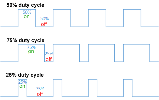
By Thewrightstuff - Own work, CC BY-SA 4.0, https://commons.wikimedia.org/w/index.php?curid=72876123
The TINKERplate can provide up to six, 10-bit PWM outputs on channels 1 through 6.
Specifications
- Frequency: 11.975Khz
- Resolution: 10 bits
- Output Voltage: Raspberry Pi +5V supply voltage
- Channels: 1, 2, 3, 4, 5, and 6
Commands
setMODE(addr,chan,'pwm') - this is the mode command for configuring a channel as a PWM output. It only needs to be issued once. Valid chan values are 1, 2, 3, 4, 5, and 6.
setPWM(addr,chan,dutyCycle) - Once a channel has been configured as a PWM output, use this command to control the duty cycle.
- The dutyCycle argument is in units of percent and has a valid range of 0.0 to 100.0.
- Valid chan values are 1, 2, 3, 4, 5, and 6.
Connections
Below is an example of the connections for a simple D to A converter. Note that because of the nonsymmetric output drive characteristics of the Digital I/O channels, it is necessary to use a buffer to produce a linear digital to analog (also referred to as D2A, D/A or DAC) response. On the output of the buffer we use a 4.7K resistor and a 100uF capacitor to make a low pass filter that results in a DC voltage that is proportional to the duty cycle.
- +5V - red wire: pin 9 on the Digital I/O block and pin 14 on the 74HCT125
- GND - black wire: pin 10 on the Digital I/O block, pin 1 and 7 the 74HCT125, and negative terminal of the capacitor
- TINKERplate Signal - gray wire: pin 6 on the Digital I/O block and pin 2 on the 74HCT125
- 4.7K Resistor - pin 3 on the 74HCT125 to positive side of 100uF capacitor

Example - Digital to Analog Converter
From the Python3 Command line interface we typed in the following commands:
|
1 2 3 4 5 6 7 |
pi@raspberrypi:~ $ python3 Python 3.7.3 (default, Apr 3 2019, 05:39:12) [GCC 8.2.0] on linux Type "help", "copyright", "credits" or "license" for more information. >>> import piplates.TINKERplate as TINK >>> TINK.setMODE(0,6,'pwm') >>> TINK.setPWM(0,6,0.0) |
Then we connected a voltmeter across the capacitor and measured that voltage as we increased the duty cycle from 0.0 to 100.0% in 10% steps. We got the following results:
| Duty Cycle | Output |
| 0 | 0.04 |
| 10 | 0.56 |
| 20 | 1.08 |
| 30 | 1.63 |
| 40 | 2.18 |
| 50 | 2.7 |
| 60 | 3.24 |
| 70 | 3.76 |
| 80 | 4.29 |
| 90 | 4.82 |
| 100 | 5.35 |
A plot of the above shows excellent linearity:

Miscelaneous
Meter Functions
We wanted a big interesting display that looked like a voltmeter for the data collected from the TINKERplate. So we created the METER function. This function allows up to 12 separate lines of data to be displayed on the screen with each line having a unique value, units, and descriptor. Note that this function is written using pygame which is already part of the default Raspian OS.
Functions
openMETER(*linesel) - before using a meter, call this function first. If no argument is included, a 1 line meter will be created. If more than 1 line of data is required, pass a number between 1 and 12 in the options linesel argument.
setMETER(value,unit,descriptor,*linesel) - update the data on the optional line of the meter with the specified value, unit, and descriptor.
setTITLE(title) - changes the default title of the METER window to the string contained in the title argument
setCOLOR(newcolor) - use this function to change the color of the meter text from the default of green. The newcolor argument is a tuple of the three colors: (red, blue, green). Each of these are 8-bit values their range is 0 to 255. To display dark yellow for example you would pass a tuple of (128, 128, 0) in the newcolor argument.
closeMETER() - closes the open on-screen meter
Examples
The code below will create a four line meter that displays the measured voltage on each of the analog inputs:
|
1 2 3 4 5 6 7 8 9 10 11 12 13 14 15 16 17 18 |
import piplates.TINKERplate as TINK import time TINK.openMETER(4) #Create a display meter on the screen with 4 lines #Change window title: TINK.setTITLE("Four Channel TINKERplate Voltmeter") #Change text color to yellow: TINK.setCOLOR((128,128,0)) while(True): values=TINK.getADCall(0) #read all of the analog inputs at once TINK.setMETER(values[0],'Volts','Input 1:',1) #Send channel 1 data to the display meter line 1 TINK.setMETER(values[1],'Volts','Input 2:',2) #Send channel 2 data to the display meter line 2 TINK.setMETER(values[2],'Volts','Input 3:',3) #Send channel 3 data to the display meter line 3 TINK.setMETER(values[3],'Volts','Input 4:',4) #Send channel 4 data to the display meter line 4 time.sleep(.5) #delay and repeat |
The above produces the following four line display on the screen:

System Functions
Below is a collection of system commands that can be useful when developing your TINKERplate code:
help() - returns a quick reference guide to all of the Python commands
getFWrev(addr) - returns the firmware revision number of the addressed TINKERplate
getHWrev(addr) - returns the hardware revision number of the addressed TINKERplate
getVersion() - returns the revision number of the TINKERplate Python module
getID(addr) - returns an ID string from the addressed TINKERplate: 'Pi-Plate TINKERplate'
RESET(addr) - resets to addressed TINKERplate to a known HW state. Use this function with caution.